VPR routing graph
Database Contents
This section will describe the prjxray database contents with respect to the routing graph.
Grid
Project X-Ray documents one or more parts. Within a part is a grid.
The grid is documented in tilegrid.json and can be accessed via the
prjxray API via the prjxray.db.Database.grid method.
Each location within the grid is a tile, which has a tile type and grid coordinate. Each instance of a tile type has the same sites, tile wires, and pips. A tile type may have zero or more sites, zero or more tile wires and zero or more pips. Pips are programmable interconnect points, and connect two tile wires together in a programmatic fashion.
A tile may also have a bits definition if the output bitstream configures this tile. A bits definition consists of a block type, a base address, the number of frames in the base address column, a word offset, and a number of words.
Routing fabric
Connection schemes
| From | To |
|---|---|
| Local Tile Wire | PIP |
| Local Tile Wire | Site Pin |
| Local Tile Wire | Remote Tile Wire |
| Remote Tile Wire | Local Tile Wire |
| Site Pin | Local Tile Wire |
| PIP | Local Tile Wire |
Tile wire
| Property | Valid choices |
|---|---|
| connections |
|
PIP
| Property | Valid choices |
|---|---|
| src_wire | Local Tile Wire |
| dst_wire | Local Tile Wire |
| is_directional | True or False |

A 7-Series part contains nodes, which consist of tile wires. Tile wires are sourced either from a site pin or a pip or a tile wire from another tile within the grid. Tile wires sink to either a site pin or a pip or a tile wire in another tile within the grid. Tile wires have not been observed to have a source and sink that are both site pins.
Tile wires that source or sink within a tile are documented in the
tile type definition, which is found in the tile_type_<tile
type>.json files. The tile type definition has a list of the tile
wires within the tile, a list of pips and a list of sites. If
the tile wires source or sink within the tile, then the tile
wire will appear in either a pip or a site definition. Tile
type definitions can be retrieved via db.Database.get_tile_type method.
All pip definitions have a src_wire and dst_wire keys, indicating what tile wire is connected to each end of the pip.
Note
A bidirectional pip will have the is_directional key set to “0”, but use src_wire and dst_wire as if it was a unidirectional pip.
Each site definition will have a site_type and dictionary of
site_pins, along with site naming information. The site_pins
dictionary maps the site_pin of the site_type to the
tile_wires within the tile. The direction of site_pin can be
found in the site_type definition, site_type_<site type>.json
file. Site type definitions can be retrieved via
db.Database.get_site_type method.
The tile wires combined with the tile’s pip list and the
site_pins definition for each site completes the routing description
for the tile. However there needs to be a relationship between tile
wires from tiles to each other. This is defined in the
tileconn.json file, provides a list of which tile wires are
connected between tiles. The tileconn.json relates tile types via
their grid coordinates.
Example:
{
     "grid_deltas": [
         0,
         1
     ],
     "tile_types": [
         "CLBLL_L",
         "CLBLL_L"
     ],
     "wire_pairs": [
         [
             "CLBLL_LL_CIN",
             "CLBLL_LL_COUT_N"
         ],
         [
             "CLBLL_L_CIN",
             "CLBLL_L_COUT_N"
         ]
     ]
 },
This reads as “a CLBLL_L that is at (x+0, y+1) from another CLBLL_L,
- Connect
CLBLL_L(x, y+1).CLBLL_LL_COUT_NtoCLBLL_L(x, y).CLBLL_LL_CIN- Connect
CLBLL_L(x, y+1).CLBLL_L_COUT_NtoCLBLL_L(x, y).CLBLL_L_CIN
The tile wire connections can be retrieved via
db.Database.get_connections.
The tile wire connections from tileconn.json, and the pips and
site pins from each tile_type_<tile type>.json provides a complete
routing graph description for a part between sites. Routing
within sites is done via pb_type architectural XML, and is not
documented as part of prjxray at this time.
VPR routing description
The previous section documented the contents of the prjxray database. Prior to describing the process of converting that database into VPR, a short discussion of the VPR routing data structures is required.
At the most basic level, VPR’s routing graph is made of nodes and edges. Edges are either configurable or static connections between nodes. Static connections are always present. Configurable connections are selected during routing. All edges must have a switch. A switch is used to describe timing information along the edge, and it determines if the switch is configurable or not. The two most common types of switches are SHORT (electrical short) and MUX.
SHORT is used to join two nodes in the routing graph, both logically and for timing purposes. SHORT’s are not configurable.
MUX is roughly equivalent to a pip. It is configurable and is used by the router. For the purposes of timing, the timing on nodes on each side of the pip are seperate. A PASS_GATE is a switch that does not do this isolation.
The detiled description about switch types can be found in VTR documentation .

So edges connect nodes together, but what are the nodes themselves? Nodes are either a source/sink (e.g. a site pin) or are routing fabric. VPR models each source or sink as 2 or more nodes. The site pin is a SINK or SOURCE. To accommodate the idea that a site pin might have multiple routing paths, the SINK or SOURCE then is connected to a IPIN or OPIN respectively. Then IPIN’s/OPIN’s are connected to other nodes. So by default, all IPIN’s connect to exactly one SINK, and all SOURCE’s connect to exactly one OPIN.
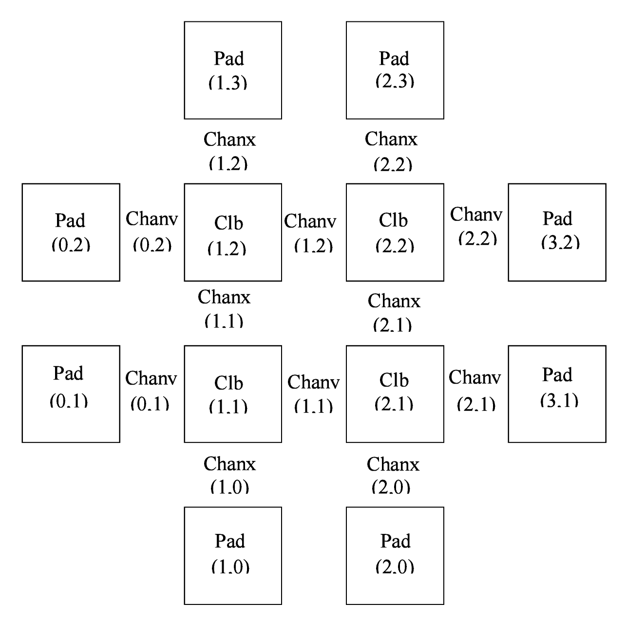
There are two routing fabric node types, CHANX and CHANY. CHANX are wires that traverse in the x-direction and CHANY are wires that traverse in the y-direction. Channels lies between tiles (see this image from the VPR routing graph description documentation). Channels cannot extended to the first or last column in the grid.
IPIN’s and OPIN’s have a direction that they point in relative to the tile they belong too. They can be on the north, east, west, south, or some combination. For example, in the image above, a pin at (1, 2) on the east side could connect to CHANY nodes at (1,2).
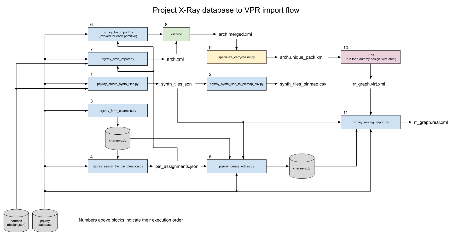
Creating a 7-series routing graph for VPR
In order to create a routing graph for VPR, several new things must be defined:
How to map the routing tile wires into VPR channels or other constructs?
Which side of the tile should site pins be assigned to connect to other tiles (in the case of direct connections like carry chains) and to VPR channels?
After the preparation work, output can be generated for VPR. 3 types of output are generated:
Tile pb_types XML’s that connect site pb_types site pins to tile wires
Architecture XML that is the grid and has direct inter-tile connections
Final routing graph XML
Click on the figure below to zoom-in:
Tile wire classification
Before channels can be formed, tile wires need to be bucketed into their purpose.
Step (1) - Group tile wires into “nodes”
The first step is to first re-form nodes that contain all the directly connected tiles wires These nodes are not VPR nodes, they are simply the collection of tile wires that are already a net (electrically equivalent).
Step (2) - Classify “nodes”
Each node then needs to be classified. The simplest classification is a channel wire, which means that pips route on and off of the node. However there are other important classifications. For example, the carry chain connection between two CLBLL_L tiles should be modelled as a tile direct connection, rather than routing onto a channel and back off. The is classified as a “edge with mux”.
The classification is broken down into the following categories:
- CHANNEL - Pips route on and off of this node.
- EDGE_WITH_MUX - Two tile wires connected by a pip.
- The first tile wire sources at a site pin, and the second tile wire sinks at a site pin.
- This captures direct inter-tile connections like carry chain wires, BRAM data cascade wires, etc.
- NULL - A node that has either no source or no sink. This wires typically occur near the edge of the grid.
- EDGES_TO_CHANNEL - A node that sources and sinks from a site pin and connects via a pip to a CHANNEL

There is another classification EDGE_WITH_SHORT, which is a direct connection between two site pins. This does not appear to occur in 7-series parts.
The reason this classification is important is that each node that is a CHANNEL must be mapped into one or more CHANX or CHANY nodes. EDGE_WITH_MUX nodes must be converted into root level architecture direct connections, and will be edges between two site pin nodes. EDGES_TO_CHANNEL will be become edges in the routing between site pins nodes and CHANX/CHANY nodes.
Channel formation
All nodes that were classified as CHANNEL type need to assigned CHANX and CHANY dimensions. This is done via make_tracks. make_tracks takes a point bag containing all of the source and sink grid locations for a particular channel. It returns straight lines such that all sources and sink grid locations can route on to or off of the channel.
Point Bag to CHANX / CHANY decomposition
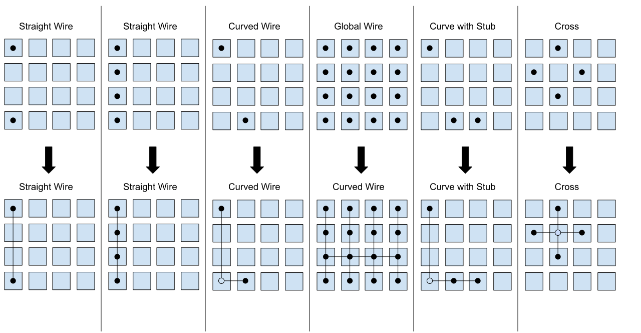
Note
Currently this logic does not optimize for the lowest required track count, instead aiming to be correct first.
Pin assignment
Because the pin directions are shared among tile types via the root pb_type that matches the tile, pin directions must be assigned taking into account the wire type attached to each site pin within the tile. For example, EDGE_WITH_MUX pins must be facing each other. EDGES_TO_CHANNEL pins must face a direction that contains their channel, per the tracks defined during channel formation.
Once pins are assigned, during tile generation, the pin assignments are used to ensure that pins can be connected into the routing graph as expected.
Tile pb_type and root architecture XML
The tile type pb_type XML files are emitted using the information from tile type, and the pin direction assignment.
The root architecture XML is emitted using the tile grid, the direct inter-tile connections from node classification.
Routing import
Routing import starts with the virtual routing graph from the architecture XML. This routing graph will have correct nodes for IPIN, OPIN, SOURCE, and SINK types. However the CHANX and CHANY nodes, and the edges to and from the CHANX and CHANY nodes will be incorrect. So the first step is to copy the portions of the virtual routing graph that are correct (block types, grid definition, nodes and edges belong to IPIN, OPIN, SOURCE, SINK).
Then channels are emitted to accommodate the tracks made during channel formation. Each track in channel formation is a new node of type CHANX or CHANY. If a node is a CHANNEL with multiple tracks, then a SHORT edge is emitted to connect the CHANX’s and CHANY’s together, making VPR treat them as electrically common.
Each pip in the grid is then matched with src and sink nodes, if possible. When pips are added to the routing graph, they also have FASM metadata to enable the pip in the bitstream.
Note
As of 2020-03-26 - Not all pips will be emitted. The current reasons are:
- Don’t currently support PIPs which connect the same src and destinations with the same switch
To avoid requiring support for IOB and clock networks for initial bringup activities, an ROI harness is used. The ROI harness brings some input/output signals to specific tile wires within the routing graph, including a clock source. During root architecture and routing import, synthetic tiles are generated that present the ROI harness sink or source, and have either an IPAD or OPAD. These tiles are purely synthetic, and are only used to describe the source or sink location within the routing graph to VPR of the ROI harness signals.
Several modifications to the standard flow are required to support the ROI and synthetics. First, nodes that contain tile wires are restricted to being either “input only” or “output only” depending on whether the synthetic tile is a clock, in pad or out pad. On “input only”, all pip that would sink to that node are skipped. On “output only”, all pip that would source from that node are skipped. Then a new synthetic edge is added connected a synthetic IPAD or OPAD tile to the relevant node. VPR can then route to or from this node just as if it was a actually IPAD or OPAD.